RS485 Breakout with 48 V Passthrough Board
Revision Status
| Revision | Status | Changes |
|---|---|---|
Rev A |
Deprecated | (Superseded by RS485 Non-Isolated Breakout Board.) |
This board has been deprecated in favour of the RS485 Non-Isolated Breakout Board.
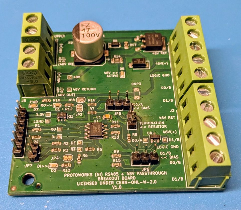
The RS485 Breakout with 48 V Passthrough Board is a non-isolated differential serial interface designed for testing robust communication over longer distances. It combines an RS485 transceiver with a high-voltage auxiliary power routing option, allowing the same cable to carry both data and power.
Features
- Transceiver: Based on the SP3485EN 3.3 V half-duplex RS485 transceiver.
- Direction Control: A solder/pin jumper links the Receiver Enable (
/RE) and Driver Enable (DE) lines, allowing a single microcontroller GPIO pin to toggle between transmit (HIGH) and receive (LOW) modes. - Selectable Termination: Onboard jumper enables a 120 Ω termination resistor across the differential A/B lines.
- Selectable Bus Biasing: Jumpers let you enable either stronger 1 kΩ or weaker 4.7 kΩ pull-up/pull-down biasing resistors to maintain a clean bus state when idle.
- 48 V Passthrough: Routes an auxiliary high-voltage supply (up to 48 V) across nodes. The 48 V path is protected by a conventional SMD fuse, a TVS diode, and P-channel MOSFET reverse-polarity protection.
- Bus Connection: Features screw terminal blocks for bus and power connection.
Pinout & Connections
Microcontroller Interface (Logic Side)
| Pin | Label | Description |
|---|---|---|
| 1 | 3.3V | 3.3 V Logic Supply (Powers the transceiver) |
| 2 | GND | Logic Ground |
| 3 | RO | Receiver Output (UART RX to MCU) |
| 4 | DI | Driver Input (UART TX from MCU) |
| 5 | DE | Driver Enable (Active High) |
| 6 | /RE | Receiver Enable (Active Low, usually tied to DE) |
Bus Side Interface (Screw Terminals)
| Terminal | Description |
|---|---|
| A | RS485 Non-inverting Line |
| B | RS485 Inverting Line |
| GND | Bus Ground |
| 48V IN | Auxiliary Power Input (Passed through via fuse/MOSFET) |
| 48V OUT | Auxiliary Power Output (To next node) |
Protection & Layout
- High-Voltage Protection: The 48 V passthrough is protected by a standard SMD fuse to isolate faults, a TVS diode to clamp surge transients, and P-channel MOSFET reverse-polarity protection.
- Layout Separation: Non-isolated, but designed with physically distinct 48 V return and logic ground copper regions to prevent power return currents from introducing noise into the logic reference ground.
Test Verification & Code
This board has been tested successfully at baud rates ranging from 300 baud up to 921,600 baud over 20 meters of Cat 6 cable using Raspberry Pi Pico 2 W nodes.
MicroPython Transmit Example
This script runs on the transmitting node, sending a counter value every second.
from machine import UART, Pin
import time

# Configure UART
uart = UART(0, baudrate=921600, tx=Pin(0), rx=Pin(1))

# Define the Driver Enable / Receiver Enable pin
de_re = Pin(2, Pin.OUT)

counter = 0

while True:
    # Enable transmit mode
    de_re.value(1)

    message = "Okay here's a counter value: " + str(counter)
    uart.write(message.encode())
    print("Sent:", message.strip())

    uart.flush()
    time.sleep(1)

    if counter >= 10:
        counter = 0
    else:
        counter += 1
MicroPython Receive Example
This script runs on the receiving node, reading the differential signal and decoding it.
from machine import UART, Pin
import time

# Configure UART
uart = UART(0, baudrate=921600, tx=Pin(0), rx=Pin(1))

# Define the Driver Enable / Receiver Enable pin
de_re = Pin(2, Pin.OUT)

# Set board to receive mode
de_re.value(0)

print("Waiting for data...")

while True:
    if uart.any():
        data = uart.read()
        try:
            decoded_text = data.decode("utf-8")
            print("Received Raw:", data)
            print("Decoded Text:", decoded_text.strip())
        except UnicodeError:
            print("Received data, but could not decode as UTF-8.")

    # Small delay to avoid hogging the CPU
    time.sleep(0.1)