RS485 Non-Isolated Breakout Board
Revision Status
| Revision | Status | Changes |
|---|---|---|
Rev A |
Active | (Initial release) |
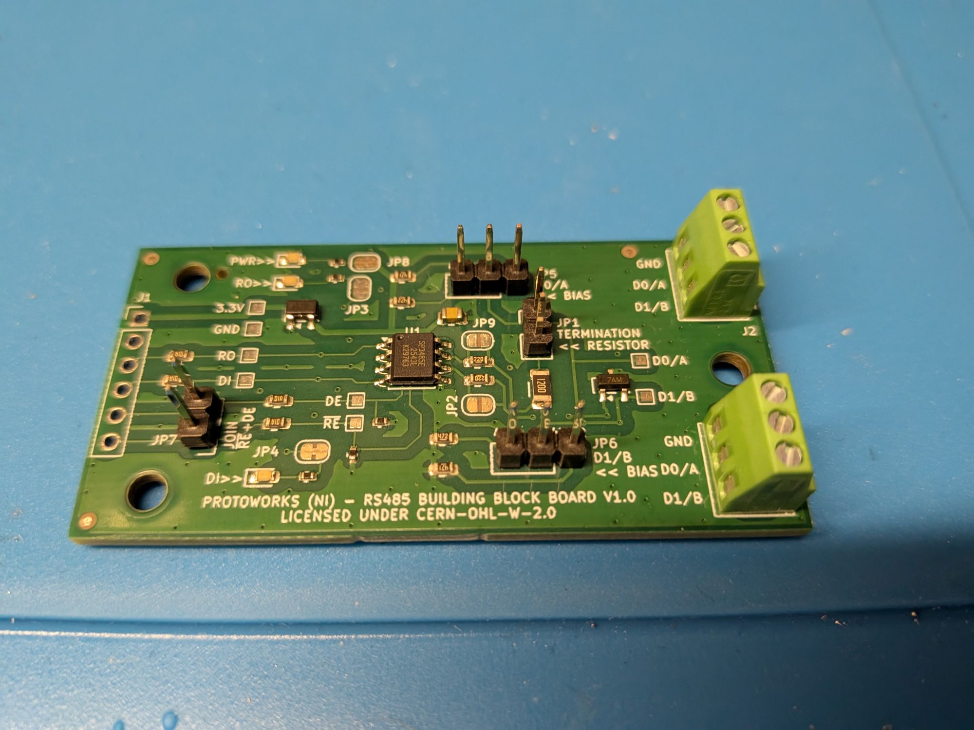
The RS485 Non-Isolated Breakout Board is a clean, compact differential serial interface designed purely for half-duplex communication. Derived from the earlier RS485 + 48 V Passthrough Board, it removes the high-voltage power routing to eliminate potential noise coupling and high-voltage risks near logic lines.
Features
- Transceiver: Based on the SP3485EN 3.3 V half-duplex RS485 transceiver.
- Compact Footprint: Uses smaller 2.54 mm pitch screw terminals and 0603/0402 passive component footprints to reduce overall board size.
- Direction Control: A pin jumper links the Receiver Enable (
/RE) and Driver Enable (DE) lines, allowing a single microcontroller GPIO to control the half-duplex direction state. - Robust Termination: Features a jumper-selectable 120 Ω termination resistor in a conservative 1206 package to comfortably handle common-mode voltages (commonly -7 V to +12 V).
- Improved Biasing: Jumper-selectable bus biasing options configured with 470 Ω and 4.7 kΩ resistors to establish a stable bus idle state.
- Brighter Indicators: RX/TX LED indicator resistors reduced from 2.2 kΩ to 470 Ω for better visibility. Solder jumpers can be cut if low-power mode is required.
- ESD Protection: Built-in TVS diode array on the differential A/B lines to protect the transceiver from electrostatic discharge and line transients.
Hardware Configuration & Pinout
Microcontroller Interface (Logic Side)
| Pin | Label | Description |
|---|---|---|
| 1 | RO | Receiver Output (UART RX) |
| 2 | DI | Driver Input (UART TX) |
| 3 | DE | Driver Enable (Active High) |
| 4 | /RE | Receiver Enable (Active Low, usually tied to DE) |
| 5 | 3.3V | 3.3 V Logic Supply |
| 6 | GND | Common Ground |
Bus Side Interface (Screw Terminals)
Two terminal blocks are provided that are electrically connected to the same lines, allowing for easy daisy-chaining of the bus.
| Pin | Terminal | Description |
|---|---|---|
| 1 | D1/B | RS485 Inverting Line |
| 2 | D0/A | RS485 Non-inverting Line |
| 3 | GND | Bus Ground Reference |
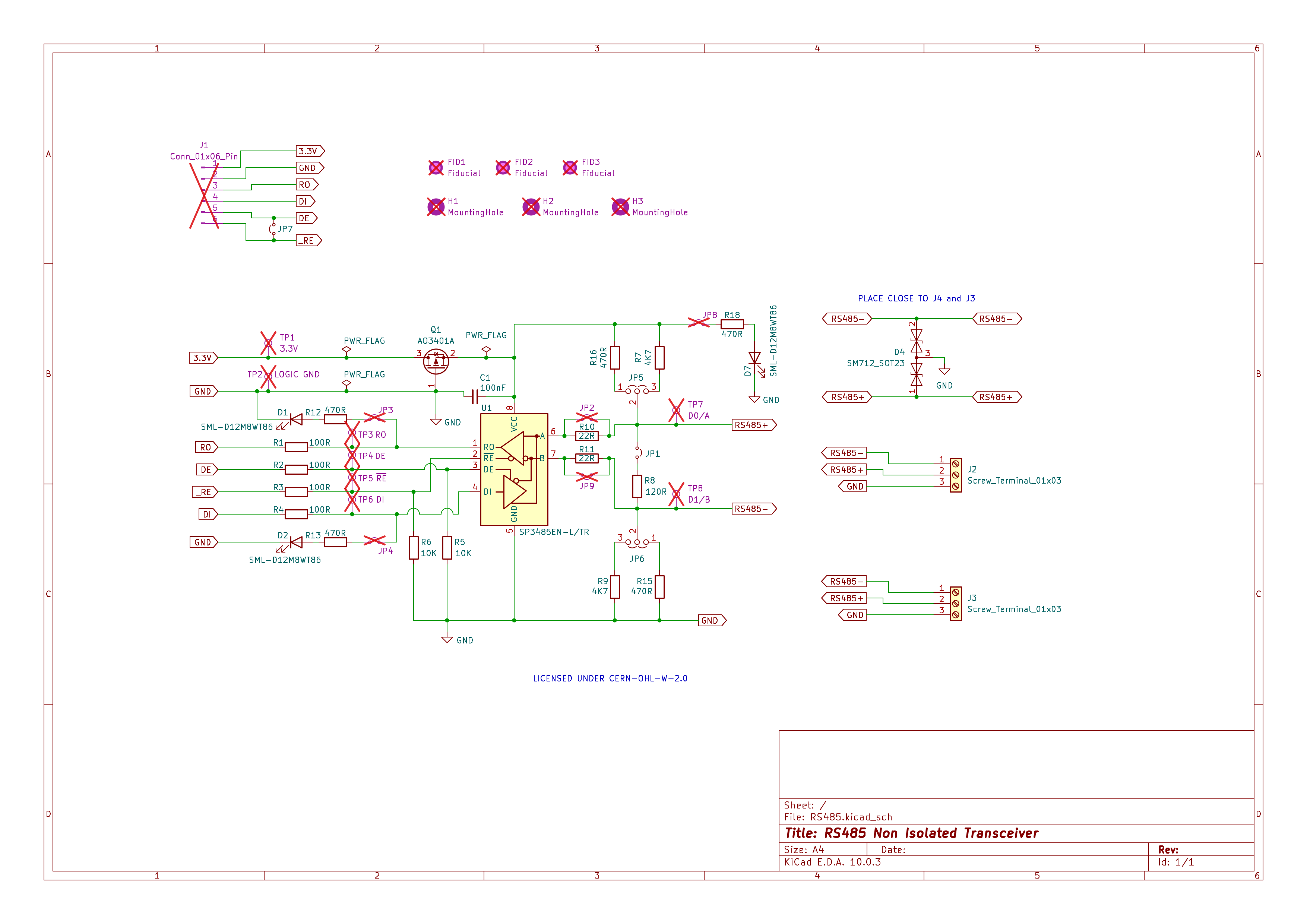
Schematic
Bill of Materials (BOM)
| Reference | Qty | Value | Footprint | LCSC Part No | MFR Part No | Description |
|---|---|---|---|---|---|---|
| C1 | 1 | 100nF | Capacitor_SMD:C_0805_2012Metric | C49678 | CC0805KRX7R9BB104 | Unpolarized capacitor, small symbol |
| D1,D2,D7 | 3 | SML-D12M8WT86 | LED_SMD:LED_0603_1608Metric | C510025 | SML-D12M8WT86 | Light emitting diode |
| D4 | 1 | SM712_SOT23 | Package_TO_SOT_SMD:SOT-23 | C7420375 | SM712 | 7V/12V, 600W Asymmetrical TVS Diode Array, SOT-23 |
| J2,J3 | 2 | Screw_Terminal_01x03 | TerminalBlock_Phoenix:TerminalBlock_Phoenix_MPT-0,5-3-2.54_1x03_P2.54mm_Horizontal | C5288763 | 1725669 | Generic screw terminal, single row, 01x03, script generated (kicad-library-utils/schlib/autogen/connector/) |
| JP1,JP7 | 2 | Jumper_2_Small_Open | Connector_PinHeader_2.54mm:PinHeader_1x02_P2.54mm_Vertical | C42431798 | PH2.54-1X2P-H25 | Jumper, 2-pole, small symbol, open |
| JP5,JP6 | 2 | Jumper_3_Open | Connector_PinHeader_2.54mm:PinHeader_1x03_P2.54mm_Vertical | C42431836 | PH2.54-1X3P-H25 | Jumper, 3-pole, both open |
| Q1 | 1 | AO3401A | Package_TO_SOT_SMD:SOT-23 | C15127 | AO3401A | -4.0A Id, -30V Vds, P-Channel MOSFET, SOT-23 |
| R1,R2,R3,R4 | 4 | 100R | Resistor_SMD:R_0603_1608Metric | C22775 | 0603WAF1000T5E | Resistor |
| R5,R6 | 2 | 10K | Resistor_SMD:R_0402_1005Metric | C25744 | 0402WGF1002TCE | Resistor |
| R7,R9 | 2 | 4K7 | Resistor_SMD:R_0603_1608Metric | C23162 | 0603WAF4701T5E | Resistor |
| R8 | 1 | 120R | Resistor_SMD:R_1206_3216Metric | C17909 | 1206WAF1200T5E | Resistor |
| R10,R11 | 2 | 22R | Resistor_SMD:R_0603_1608Metric_Pad0.98x0.95mm_HandSolder | C23345 | 0603WAF220JT5E | Resistor |
| R12,R13,R18 | 3 | 470R | Resistor_SMD:R_0402_1005Metric | C25117 | 0402WGF4700TCE | Resistor |
| R15,R16 | 2 | 470R | Resistor_SMD:R_0603_1608Metric | C23179 | 0603WAF4700T5E | Resistor |
| U1 | 1 | SP3485EN-L/TR | Package_SO:SOIC-8_3.9x4.9mm_P1.27mm | C8963 | SP3485EN-L/TR | Industrial 3.3V Low Power Half-Duplex RS-485 Transceiver 10Mbps, SOIC-8 |
Test Verification & Code
This board has been tested successfully at baud rates ranging from 300 baud up to 921,600 baud over 20 meters of Cat 6 cable using Raspberry Pi Pico 2 W nodes.
MicroPython Transmit Example
This script runs on the transmitting node, sending a counter value every second.
from machine import UART, Pin
import time

# Configure UART
uart = UART(0, baudrate=921600, tx=Pin(0), rx=Pin(1))

# Define the Driver Enable / Receiver Enable pin
de_re = Pin(2, Pin.OUT)

counter = 0

while True:
    # Enable transmit mode
    de_re.value(1)

    message = "Okay here's a counter value: " + str(counter)
    uart.write(message.encode())
    print("Sent:", message.strip())

    uart.flush()
    time.sleep(1)

    if counter >= 10:
        counter = 0
    else:
        counter += 1
MicroPython Receive Example
This script runs on the receiving node, reading the differential signal and decoding it.
from machine import UART, Pin
import time

# Configure UART
uart = UART(0, baudrate=921600, tx=Pin(0), rx=Pin(1))

# Define the Driver Enable / Receiver Enable pin
de_re = Pin(2, Pin.OUT)

# Set board to receive mode
de_re.value(0)

print("Waiting for data...")

while True:
    if uart.any():
        data = uart.read()
        try:
            decoded_text = data.decode("utf-8")
            print("Received Raw:", data)
            print("Decoded Text:", decoded_text.strip())
        except UnicodeError:
            print("Received data, but could not decode as UTF-8.")

    # Small delay to avoid hogging the CPU
    time.sleep(0.1)